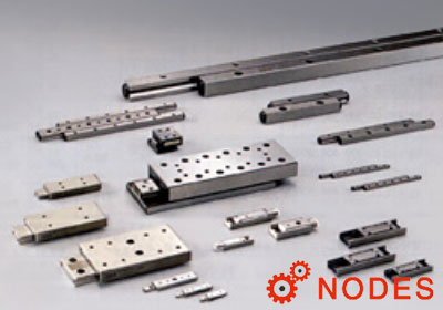
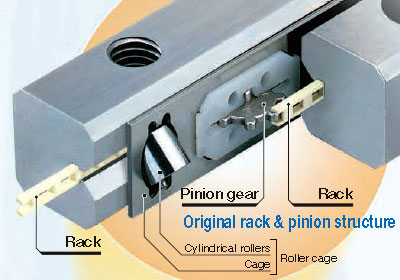
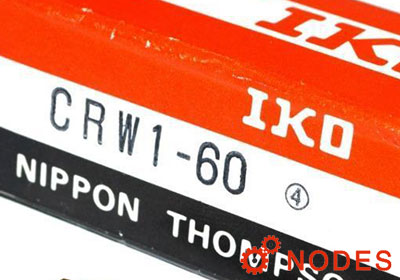
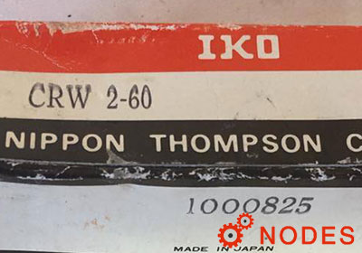
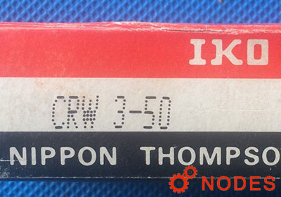
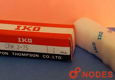
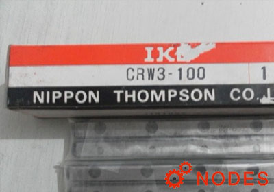
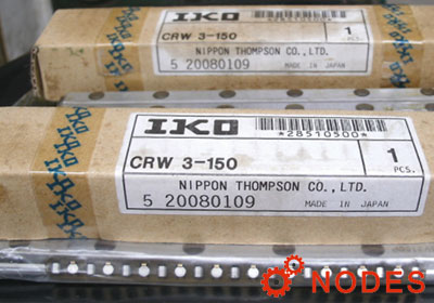
The specifications of IKO crossed roller way guides CRWG series, CRWG...H series, and CRW series are indicated by the identification number. Indicate the identification number, consisting of a model code, a dimension, a part code, a material code, a classification symbol, and any supplemental codes for each specification to apply.
For example: CRW12-300 C14
| CRW | model code |
| 12 | size, dimension |
| 300 | way length |
| C14 | number of cylindrical rollers |
1, Model
- CRWG: Anti-Creep cage crossed roller way
- CRWG...H: Anti-Creep cage crossed roller way H
- CRW: Crossed roller way
- CRWM: Crossed roller way
2, Size
1, 2, 3, 4, 6, 9, 12, 15, 18, 24
3, Way length
The way length is indicated in mm. IKO CRW series can be combined with a way of different length.
Combination of standard type
This combination consists of two short ways, two long ways, and two roller cages, as a set.
The number of rollers incorporated into a roller cage shall be standard number of short ways (number described in the dimension table) but the number of rollers may be specified.
Example: CRW 6 - 300 X 400 C24
- 300: Length of short way: 300mm
- 400: Length of long way: 400mm
Combination of module type
This combination consists of one center way, two ways, and two roller cages, as a set.
The number of rollers incorporated into a roller cage shall be standard number of short ways (number described in the dimension table) but the number of rollers may be specified.
Example: CRWM 3 - 200 X 150 C20
- 200: Length of center way: 200mm
- 150: Length of outside way: 150mm
4, Number of cylindrical rollers
- No symbol: This is represents the number of cylindrical rollers
- Cxx: Incorporated into a CRW series cage. if not directed, the number of cylindrical rollers indicated in the dimension table shall be incorporated in a roller cage.
5, Material type
- No symbol: High carbon steel made.
- SL: Stainless steel made.
6, Accuracy class
No symbol: Standard.
SP: Super precision.
7, Special specification
- B: Special mounting screw. Preload adjusting-side way can be moved by adjusting the preload. Allowance for movement is required between a way fixing screw and mounting hole, but special mounting screws are provided for the cases where enough allowance is not provided or a fixing screw should be mounted from the way side.
- M: High rigidity roller cage. The cage is changed into a high rigidity copper ally-made cage designed to suit vertical axis application. This cage has a structure to prevent a roller from dropping off in one-side direction. For using a high rigidity roller cage for vertical axis application, it is recommended to use the cage in combination with end stopper SB.
- SA: End stopper SA. When the stroke frequency is high and cage creep may be caused by the vibration and non-uniformly varying load, the end screw is changed into end stopper SA.
- SB: End stopper SB. When using a high rigidity roller cage for vertical axis application, the end screw is changed into end stopper SB to regulate the cage stroke at the end.
- U: Wiper seal. In order to prevent foreign substances from entering into a raceway, the wiper seal is changed into the one with a function of end stopper SB.


