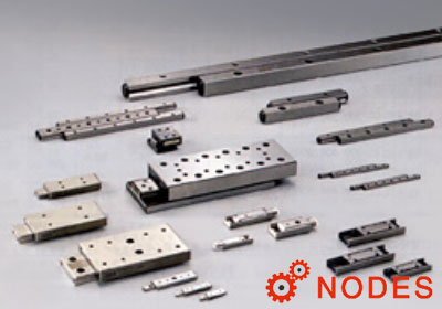
Mounting example of IKO crossed roller way guides CRW series
For mounting IKO crossed roller way guides CRW series, generally follow the procedure below.
1 Preparation for mounting
IKO crossed roller way guides CRW series are packed by set (4 ways and 2 pairs of roller cages). Be careful not to mix with other sets.
Remove end screws and end stopper, clean up each part with clean wash fluid and then apply rust prevention and lubrication oil.
2 Cleanup of mounting surface
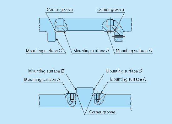
Mounting surface
Remove burrs and blemishes on the machine mounting surface with an oil-stone, etc. Be careful about corner groove on the mounting surface, too.
Wipe off dust and dirt with clean cloth and apply rust prevention and lubrication oil lightly.
3 Mounting of bed-side way
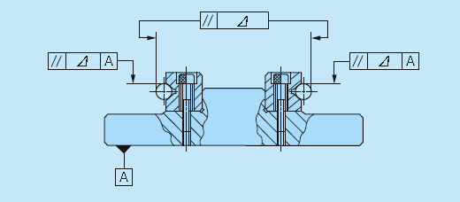
Accuracy of IKO crossed roller way guides mounting
Properly align the way with mounting surface and temporarily tighten fixing screws evenly to the tightening torque.
While making the way sticking to B surface tight, fully tighten the screws to the specified torque.
When high running accuracy is required, fully and evenly tighten them to the specified torque while checking the parallelism of the raceway along the full length of the way.
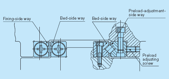
4 Mounting of table-side way
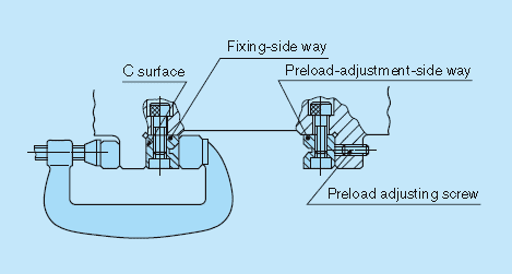
Mounting of table-side way
Properly align the fixing-side way with mounting surface and temporarily tighten fixing screws evenly to the tightening torque.
While making the fixing-side way sticking to C surface tight, fully tighten the screws to the specified torque.
Set back the preload adjusting screws in advance, make the preload-adjusting-side way sticking to the mounting surface, and then temporarily tighten fixing screws lightly to the even torque.
5 Operation of table and bed
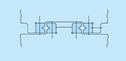
Position alignment before operation
Make alignment of the position in height and cross direction so that the roller cage can be inserted between the table-side way and bed-side way.
Carefully insert the roller cage and assembly it at approximate center of the way length. At this point, be careful not to deform the cage.
Mount end screws and end stopper of each way.
Push the entire table against the preload adjusting screws and tighten the preload adjusting screws to make temporary adjustment until the clearance between ways becomes zero.
Fully stroke the table softly and correct the roller cage position to the center.
6 Preload adjustment
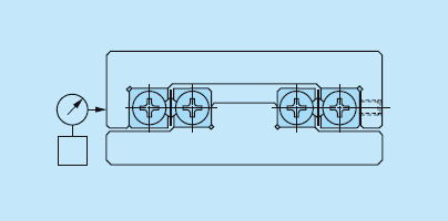
Example of preload adjustment method
Preload adjustment is performed with fixing screws of the preload-adjusting-side way tightened temporarily.
Preload adjustment is started from the preload adjusting screw at the center of way length and then both ends in turn.
While measuring the clearance on the table sides, tighten the preload adjusting screws subsequently until deflection of the dial gauge stops. Measure the tightening torque for preload adjusting screws at this point.
When adjusting preload adjusting screw near either end, stroke the table softly and check that the cylindrical roller is on the preload adjusting screw section.
After the above procedure, the clearance becomes zero or in slight preload state, but preload is still not adjusted evenly. With the same procedure again, re-adjust all the preload adjusting screws evenly to the torque previously measured.
7 Full tightening of preload-adjustment-side way
Fixing screws are lightly tightened to even torque. As with preload adjusting screws, temporarily fix them to torque similar to the specified torque in turn from the way center to both ends.
When tightening fixing screws near either end, stroke the table softly and check that the cylindrical roller is on fixing screw section.
Finally with the same procedure, fully tighten all the fixing screws evenly to the specified torque.
8 Check after assembly
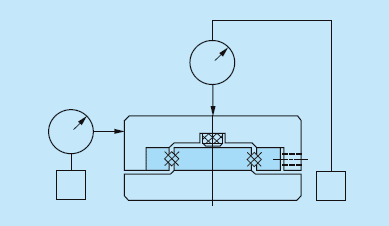
Accuracy check after assembly
Fully stroke the table softly and check that running is smooth without abnormal noise.
Measure the table upper and side surfaces with dial gauge or the like and check the running accuracy.