
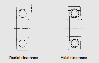
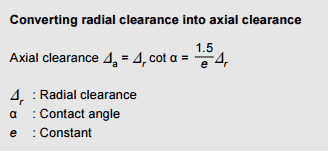
Internal clearance is the distance which the two rings of a non-installed bearing can move when they are pushed in opposite directions. A distinction is made between radial and axial clearance.
Radial clearance is measured perpendicular to a bearing’s central axis, while axial clearanceis measured along the central axis. The distance between one final position and the other is measured.
Internal clearance has a major impact on the operating performance of bearings. It affects factors such as their service life, vibration, noise level and heat generation.
Measured and geometric internal clearance
To obtain actual values, the theoretical clearance is measured by applying a defined measuring load to the bearing. This measured value is always slightly higher than the theoretical clearance – also known as the geometric clearance. The difference between the two figures corresponds to the elastic deformation caused by the measuring load.
The theoretical clearance can be calculated by subtracting the amount of elastic deformation from the measured clearance. This elastic deformation is minimal in the case of roller bearings, where the internal clearance defined prior to installation and the theoretical clearance are the same.
Factors affecting internal clearance
Reduction in radial clearance due to the fit
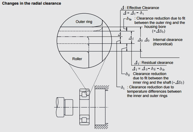
If the inner ring or outer ring is mounted on the shaft or in the housing with an interference fit, the radial clearance is reduced when the inner ring expands or the outer ring contracts. This reduction varies for different bearing types and sizes, and depends on the shaft or housing design. The reduction is approximately 70 to 90% of the interference. After subtracting these reductions (δfe and δfi) from the theoretical clearance (∆0), the play is referred to as residual clearance (∆f).
Reduction in radial play due to differences in temperature between the inner and outer rings
The frictional heat generated during operation is conducted along the shaft and through the housing until it reaches the outside. As housings are better at conducting heat than shafts due to their mass, the temperature of the inner ring and the rolling elements is normally 5 to 10 °C higher than that of the outer ring. If the shaft heats up or the housing is cooled down, the resulting difference in temperature between the inner and outer rings causes the radial play to decrease. Subtracting δt from the residual clearance (∆f) gives us the effective internal clearance (∆).
The following equations can be used to calculate the extent of this reduction:
δt = α∆t De
δt : Radial clearance reduction due to temperature differences between the inner and outer rings (mm)
α : Linear thermal expansion coefficient for bearing steel = 12.5 ∙ 10−6 (1/°C)
∆t : Difference in temperature between the inner and outer rings (°C)
De : Outer ring raceway diameter (mm)
For ball bearings: De = (4D+d)
For roller bearings: De = (3D+d)
A bearing with an effective clearance of 0 or a low positive number should be chosen. If single-row angular contact ball bearings or tapered roller bearings are mounted as a duplex set, the effective clearance should be minimal (unless a preload is needed). If two cylindrical roller bearings with a shoulder on one side are used opposite one another, a level of axial clearance must be selected which enables free expansion of the shaft.
| Operating conditions | Examples | Internal clearance |
|---|---|---|
| Severe shaft deflection | Semi-floating wheel bearings in cars | C5 or similar |
| Steam flow through hollow shafts or pressure bars exposed to heat |
Dry end of paper machines Conveyor rollers in rolling mills |
C3, C4 C3 |
| High impact loads and vibrations, or both inner and outer rings with an interference fit |
Traction motors for trains Vibrating screens Hydraulic clutches Gearboxes for tractors |
C4 C3, C4 C4 C4 |
| Loose-fitting inner and outer rings | Roll tenons for rolling mills | C2 or similar |
| Very quiet, vibration-free running | Small motors with special specifications | C1, C2, CM |
| Set play to avoid shaft deflection etc. | Main spindle of lathes | CC9, CC1 |
Preload – a special type of negative clearance
Normally, bearings retain a certain amount of internal play when they are operating. However, in some cases it is advantageous to set negative clearance to increase the bearing arrangement’s rigidity. This is called preloading.
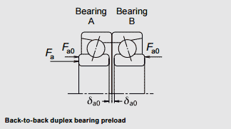
Preloads are designed for use with bearings whose play can be set during installation, e.g. angular-contact ball bearings and tapered roller bearings. Generally, two bearings are mounted in a face-to-face or back-to-back configuration to create a duplex set with a preload.
The purpose of a preload in typical applications
-
Main shafts of machine tools and precision instruments
Holding the bearings in their exact position – both radially and axially – as well as maintaining the shaft’s rotational accuracy and increasing rigidity. -
Main shafts of machine tools, pinion shafts in car gearboxes
Increasing bearing rigidity and optimising gear meshing. -
Small electric motors
Reducing noise caused by axial vibration and resonance. -
High-speed or high-acceleration applications with angular-contact or deep grove ball bearings
Preventing slippage between the rolling elements and the raceways caused by gyratory moments -
Axial ball bearings and self-aligning spherical roller thrust bearings mounted on a horizontal shaft
Keeping the rolling elements in the correct position with the bearing rings.
Types of preload
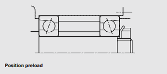
1a) Position preload
A position preload is achieved by fixing two axially opposed bearings in such a way that a preload is imposed on them. Once they have been fixed in place, their position remains unchanged during operation.
In practice, three methods are normally used to obtain a position preload:
- Installing a duplex bearing set with previously adjusted stand-out dimensions and axial clearance
- Using a spacer or shim of the correct size to obtain the required spacing and preload
- Utilising screws or nuts to set the axial preload. In this case, the starting torque should be measured to verify the proper preload.
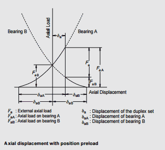
1b) Position preload and rigidity
When the inner rings of bearings A and B are fixed axially, the space measuring 2 δa0 is liminated. A preload of Fa0 is imposed on each bearing.
Bearing rigidity – i.e. the relationship between load and axial displacement – with a given axial load Fa imposed on a duplex set.
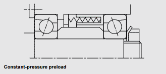
2a) Constant-pressure preload
A constant-pressure preload is achieved using a coil or leaf spring. Even if the relative position of the bearings changes during operation, the size of the preload remains relatively constant.
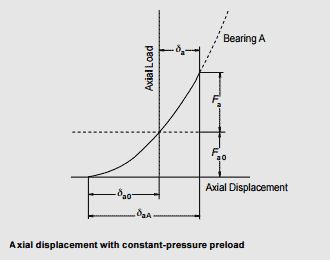
2b) Constant-pressure preload and rigidity
The diagram shows the rigidity of duplex bearings under a constant-pressure preload. The deflection curve of the spring is nearly parallel to the horizontal axis because the rigidity of the springs is lower than that of the bearing. As a result, the rigidity under a constant-pressure preload is approximately equal to that for a single bearing with a preload of Fa0 applied to it.
Comparison of bearing rigidity and preloading methods
Position preload and constant-pressure preload can be compared as follows:
- When both preloads are equal, the position preload provides greater bearing rigidity. In other words, the deflection due to external loads is less for bearings with a position preload.
- Constant-pressure preloads are more suitable for high-speed applications, to prevent axial vibration and for use with thrust bearings on horizontal shafts.
-
When a position preload is used, the preload varies depending on the following factors:
Variation in the axial expansion due to temperature differences between the shaft and the housing
Variation in radial expansion due to temperature differences between the inner and outer rings
Deflection due to load - When using a constant-pressure preload, variation is minimal because the effects of shaft expansion and contraction are negligible.
Amount of preload
If the preload is larger than necessary, it can result in unwanted heat generation, increased torque and a shorter service life. The amount of preload should be carefully calculated, taking the operating conditions and the purpose of the preload into account. In extreme cases, the bearing may last for just a few hours.
(1) Preloading duplex angular-contact ball bearings
As a general rule, an extra light or light preload should be selected for grinding spindles and the main shafts of machining centres. A medium preload should be adopted for the main shafts of lathes requiring rigidity. When speeds result in a value of Dpw ∙ n (dmn value) higher than 500,000 the preload should be very carefully considered and selected.
(2) Preloading axial ball bearings
When the balls in axial ball bearings rotate at relatively high speeds, slippage may occur due to gyratory moments acting on the balls. The larger of the two values obtained from the equations should be adopted as the minimum axial load in order to prevent this kind of slippage.
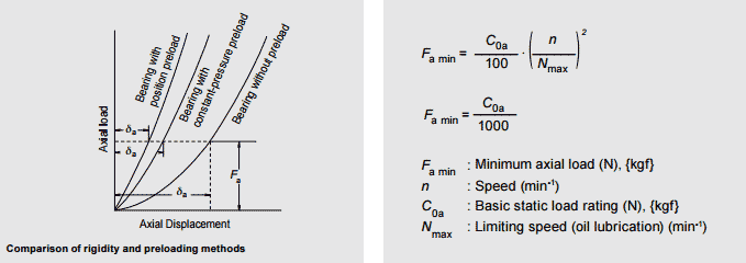
(3) Preloading self-aligning spherical roller thrust bearings
When self-aligning spherical roller thrust bearings are used, damage such as broken rings may occur due to slippage between the rollers and the outer-ring raceway. The minimum axial load necessary to prevent such slippage (Fa min) can be calculated using the following equation:
Fa min = C0a / 1000