J-Line part numbers
Some ABMA (inch) part numbers are designed with metric envelope dimensions. The J prefix letter is used in conjunction with the ABMA part-numbering system to identify metric-dimensioned and toleranced inner rings and outer rings. The J-prefix is shown before the ABMA prefix letters. J-Line bearings are referred to as inch bearings in metric bore, O.D. and width.
For example: J HM 5 226 49 ---
- J: Metric, component designator
- HM: series prefix
- 5: Angularlty
- 226: Basic series indication
- 49: Component designator
- ---: Modification suffix
J-Prefix
A range of metric bearings originally designed by The Timken Company also were included in the ISO 355 plan. These Timken bearings are specifically application-oriented and are designed for optimum performance. Depending on application and type of load, thrust and/or radial, the bearing with the optimum angle and section can be selected. For example, pinion bearings have a steep angle, whereas bearings for machine tools are generally designed with a shallow angle and a light section. These bearings as below demonstrates this feature for 55 mm (2.1654 in.) bore bearings.
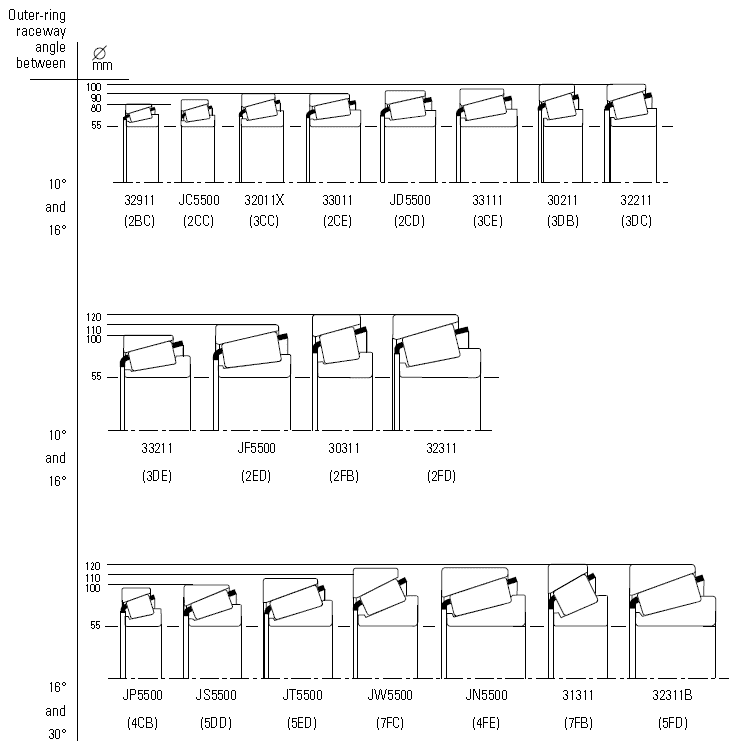
Comparison of metric bearing designs for 55 mm (2.1654 in.) bore.
These bearings also are identified with a J-prefix, which indicates a metric dimensioned and toleranced bearing.
For example: J P 100 49
- J: Metric, component designator
- P: Duty
- 100: inner-ring bore diameter
- 49: Component designator
1, Duty
Indicates application type:
- C, D & F = general purpose
- N = combination of general purpose and pinion
- P = high speed
- S & T = pinions
- W = high axial loads
2, Inner-ring bore
The inner-ring bore metric diameter is included in the part-number designation of both the inner ring and outer rings.
3, Component designator
Same identification as in the ABMA part-numbering system.
ISO 355 part numbering
As dimensions given by the ISO 15 general plan were not found to be optimal for tapered roller bearings, ISO introduced a new numbering system for tapered roller bearings in ISO 355. The numbering system of ISO 355 uses three alphanumeric fields to define a dimension series. The bearing part number is then defined by adding the inner-ring diameter in mm after the dimension series. Although the original metric part numbers were assigned a new designation in the ISO 355 plan, the original part number is still used.
For example: T 4 C B 100
- T: symbol for tapered roller bearings
- 4: angle series designation
- C: diameter series designation
- B: width series designation
- 100: bearing bore diameter (mm)
1, Angle series designation
| Angle series designation | a | |
|---|---|---|
| Over | Incl. | |
| 1 | Reserved for future use | |
| 2 | 10° | 13° 52’ |
| 3 | 13° 52’ | 15° 59’ |
| 4 | 15° 59’ | 18° 55’ |
| 5 | 18° 55’ | 23° |
| 6 | 23° | 27° |
| 7 | 27° | 30° |
2, diameter series designation
| diameter series designation | D/d0.77 | |
|---|---|---|
| over | incl. | |
| A | Reserved for future use | |
| B | 3.4 | 3.8 |
| C | 3.8 | 4.4 |
| D | 4.4 | 4.7 |
| E | 4.7 | 5 |
| F | 5 | 5.6 |
| G | 5.6 | 7 |
3, width series designation
| width series designation | T/(D-d)0.95 | |
|---|---|---|
| over | incl. | |
| A | Reserved for future use | |
| B | 0.5 | 0.68 |
| C | 0.68 | 0.8 |
| D | 0.8 | 0.88 |
| E | 0.88 | 1 |