
The guidance and support of a rotating shaft requires at least two bearings arranged at a certain distance from each other. Depending on the application, a decision is made between a locating/non-locating bearing arrangement, an adjusted bearing arrangement and a floating bearing arrangement.
Locating/non-locating bearing arrangement
On a shaft supported by two radial bearings, the distances between the bearing seats on the shaft and in the housing frequently do not coincide as a result of manufacturing tolerances. The distances may also change as a result of temperature increases during operation. These differences in distance are compensated in the non-locating bearing.
Non-locating bearings
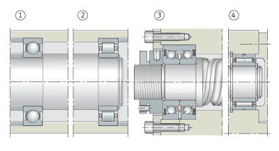
Locating/non-locating bearing arrangements
(1)Locating bearing: Deep groove ball bearing
(2)Non-locating bearing: Cylindrical roller bearing NU
(3)Locating bearing: Axial angular contact ball bearing ZKLN
(4)Non-locating bearing: Needle roller bearing NKIS
Ideal non-locating bearings are cylindrical roller bearings with cage N and NU or needle roller bearings. In these bearings, the roller and cage assembly can be displaced on the raceway of the bearing ring without ribs.
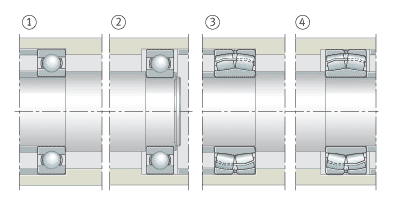
Locating/non-locating bearing arrangements
(1)Locating bearing: Deep groove ball bearing
(2)Non-locating bearing: Deep groove ball bearing
(3)Locating bearing: Spherical roller bearing
(4)Non-locating bearing: Spherical roller bearing
All other bearing types, for example deep groove ball bearings and spherical roller bearings, can only act as non-locating bearings if one bearing ring has a fit that allows displacement. The bearing ring subjected to point load therefore has a loose fit; this is normally the outer ring.
Locating bearings
The locating bearing guides the shaft in an axial direction and supports external axial forces. In order to prevent axial stresses, shafts with more than two bearings have only one locating bearing. The type of bearing selected as a locating bearing depends on the magnitude of the axial forces and the accuracy with which the shafts must be axially guided.
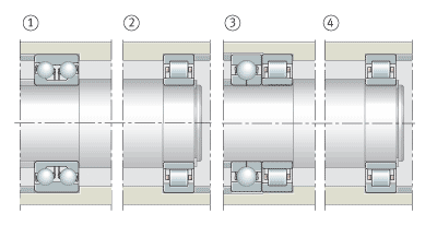
Locating/non-locating bearing arrangements
(1)Locating bearing: Double row angular contact ball bearing
(2)Non-locating bearing: Cylindrical roller bearing NU
(3)Locating bearing: Four point contact bearing and cylindrical roller bearing
(4)Non-locating bearing: Cylindrical roller bearing NU
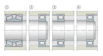
Locating/non-locating bearing arrangements
(1)Locating bearing: Two tapered roller bearings
(2)Non-locating bearing: Cylindrical roller bearing NU
(3)Locating bearing: Cylindrical roller bearing NUP
(4)Non-locating bearing: Cylindrical roller bearing NU
A double row angular contact ball bearing, for example, will give closer axial guidance than a deep groove ball bearing or a spherical roller bearing. A pair of symmetrically arranged angular contact ball bearings or tapered roller bearings used as locating bearings will provide extremely close axial guidance.
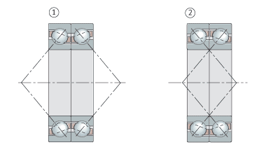
Locating bearing arrangements
(1)Pair of angular contact ball bearings of universal design, O arrangement
(2)Pair of angular contact ball bearings of universal design, X arrangement
Angular contact ball bearings of the universal design give particular advantages. The bearings can be fitted in pairs in any O or X arrangement without shims. Angular contact ball bearings of the universal design are matched such that, in an X or O arrangement, they have a low axial internal clearance (design UA), zero clearance (UO) or slight preload (UL).
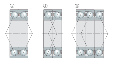
Locating bearing arrangements
(1)Spindle bearings of universal design, O arrangement
(2)Spindle bearings of universal design, X arrangement
(3)Spindle bearings of universal design, Tandem O arrangement
Spindle bearings of the universal design UL have slight preload when fitted in an X or O arrangement (designs with higher preload are available by agreement).
In gearboxes, a four point contact bearing is sometimes fitted directly adjacent to a cylindrical roller bearing to give a locating bearing arrangement. The four point contact bearing, without radial support of the outer ring, can only support axial forces. The radial force is supported by the cylindrical roller bearing.
If a lower axial force is present, a cylindrical roller bearing with cage NUP can also be used as a locating bearing.
No adjustment or setting work with matched pairs of tapered roller bearings
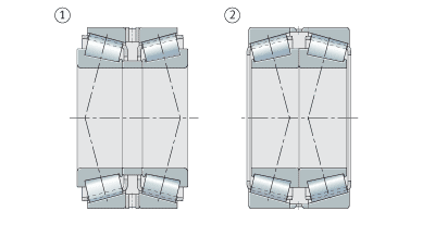
Locating bearing arrangements
(1)Pair of tapered roller bearings, O arrangement
(2)Pair of tapered roller bearings, X arrangement
Fitting is also made easier with a matched pair of tapered roller bearings as a locating bearing (313..-N11CA). They are matched with appropriate axial internal clearance so that no adjustment or setting work is required.
Adjusted bearing arrangement
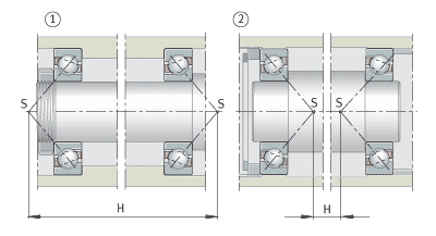
Adjusted bearing arrangement
(1)Angular contact ball bearing, O arrangement
(2)Angular contact ball bearing, X arrangement
S = apexes of the contact cones
H = support distance
These bearing arrangements normally consist of two symmetrically arranged angular contact ball bearings or tapered roller bearings. During fitting, one bearing ring is displaced on its seat until the bearing arrangement achieves the required clearance or the necessary preload.
Area of application
Due to this adjustment facility, the adjusted bearing arrangement is particularly suitable where close guidance is required, for example in pinion bearing arrangements with spiral toothed bevel gears and spindle bearing arrangements in machine tools.
X and O arrangements
Adjusted bearing arrangement
(1)Angular contact ball bearing, O arrangement
(2)Angular contact ball bearing, X arrangement
S = apexes of the contact cones
H = support distance
A fundamental distinction is drawn between the O arrangement and the X arrangement of the bearings. In the O arrangement, the cones and their apexes S formed by the contact lines point outwards; in the X arrangement, the cones point inwards. The support base H, in other words the distance between the apexes of the contact cones, is larger in the O arrangement than in the X arrangement. The O arrangement therefore gives the lower tilting clearance.
Influence of thermal expansion in X and O arrangements
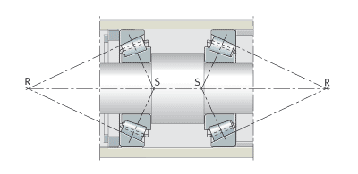
Adjusted bearing arrangement
Tapered roller bearings in X arrangement
S = apexes of the contact cones
R = roller cone apexes
When setting the axial internal clearance, thermal expansion must be taken into consideration. In the X arrangement a temperature differential between the shaft and housing always leads to a reduction in the internal clearance (assuming the following preconditions: shaft and housing of identical material, inner ring and complete shaft at identical temperature, outer ring and complete housing at identical temperature).
In the O arrangement, a distinction is drawn between three cases:
- The roller cone apexes R, i.e. the intersection points of the extended outer ring raceway with the bearing axis, coincide: the internal clearance set is maintained.
- The roller cones overlap and there is a short distance between the bearings: the axial internal clearance is reduced.
- The roller cones do not meet and there is a large distance between the bearings: the axial internal clearance is increased.
Elastic adjustment
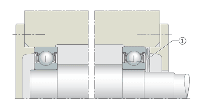
Adjusted bearing arrangement
Deep groove ball bearing preloaded by curved spring washer
(1)Curved spring washer
Adjusted bearing arrangements can also be achieved by preloading using springs. The elastic adjustment method compensates for thermal expansion. It can also be used where bearing arrangements are at risk of vibration while stationary.
Floating bearing arrangement
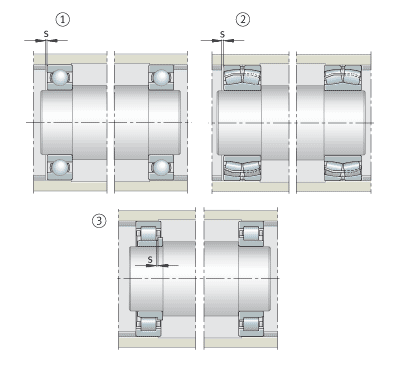
Floating bearing arrangements
(1)Two deep groove ball bearings
(2)Two spherical roller bearings
Two cylindrical roller bearings NJ
s = axial clearance
The floating bearing arrangement is an economical solution where close axial guidance of the shaft is not required. The construction is similar to that of the adjusted bearing arrangement.
In the floating bearing arrangement, however, the shaft can be displaced in relation to the housing to the extent of the axial clearance s. The value s is defined as a function of the required guidance accuracy such that the bearings are not axially clamped even under unfavourable thermal conditions.
Suitable bearings
Suitable bearing types for the floating bearing arrangement include deep groove ball bearings, self-aligning ball bearings and spherical roller bearings.
In each of the bearings one ring, usually an outer ring, has a fit that allows displacement.
In floating bearing arrangements and cylindrical roller bearings with cage NJ, the length compensation takes place within the bearings. The inner and outer rings can have tight fits.
Tapered roller bearings and angular contact ball bearings are not suitable for a floating bearing arrangement, since they must be adjusted in order to run correctly.