
Bearing seats on shafts and in housings, and components which locate a bearing axially, have a significant impact on SKF bearing performance. To fully exploit the load carrying ability of a SKF bearing, its rings or washers should be fully supported around their complete circumference and across the entire width of the raceway. Bearing seats should be manufactured to adequate geometrical and dimensional tolerances and be uninterrupted by grooves, holes or other features. Please refer to SKF bearing selection.
In this section you can find recommendations and requirements for designing bearing interfaces, including:
- criteria when selecting bearing fits
- recommended fits for standard conditions
- tables to help determine minimum, maximum and probable values of clearance or interference between the bearing and its seat
- recommendations for specifying geometrical tolerances of bearing seats
- recommendations for the axial support of bearing rings
- further design considerations for bearing interfaces
The ISO tolerance system
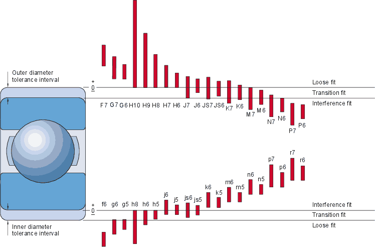
Fits for rolling bearings are typically specified with standard tolerance classes for holes and shafts as described in ISO 286-2. As SKF bearings are typically manufactured to ISO tolerances, the selection of the tolerance class for the bearing seat determines the fit. illustrates the position and width of the tolerance intervals of commonly used tolerance classes relative to the bearing bore and outside diameter tolerances. The figure above is valid for bearings with Normal tolerances and of medium size. It is important to note that the ISO tolerance classes for rolling bearings and for holes and shafts are different. The tolerances for each size vary over the full range of actual sizes. You should therefore select the respective tolerance classes for bearing seats based on the actual bearing size for your application.
Selecting fits
Fits can be selected by following the recommendations for bearing seat diameter tolerances. These recommendations will provide adequate solutions for the majority of applications. However, they do not cover all details of a specific application and so you may find that adjustments may be necessary. When selecting fits, you should consider the following topics.
Conditions of rotation
|
Operating conditions |
Load condition |
Recommended fits |
|
Rotating inner ring |
Rotating inner ring load |
Interference fit for the inner ring |
|
Stationary outer ring |
Stationary outer ring load |
Loose fit for the outer ring possible |
|
Constant load direction |
||
|
Rotating inner ring |
Stationary inner ring load |
Loose fit for the inner ring possible |
|
Stationary outer ring |
Rotating outer ring load |
Interference fit for the outer ring |
|
Load rotates with the inner ring |
||
|
Stationary inner ring |
Stationary inner ring load |
Loose fit for the inner ring possible |
|
Rotating outer ring |
Rotating outer ring load |
Interference fit for the outer ring |
|
Constant load direction |
||
|
Stationary inner ring |
Rotating inner ring load |
Interference fit for the inner ring |
|
Rotating outer ring |
Stationary outer ring load |
Loose fit for the outer ring possible |
|
Load rotates with outer ring |
Conditions of rotation refer to the relative motion between a bearing ring and the load acting upon it. Essentially, there are three different conditions:
- rotating load
- stationary load
- direction of load indeterminate
Rotating loads occur where either the bearing ring or the applied load is stationary while the other rotates. A bearing ring mounted with a loose fit will creep on its seat when subjected to a rotating load, and this can lead to fretting corrosion and eventually wear. To prevent this from happening, an adequate interference fit, between the ring subjected to rotating load and its seat, is required.
For the purpose of selecting fits, loads that oscillate (such as loads acting on connecting rod bearings) are considered to be rotating loads.
Stationary loads occur where both the bearing ring and the applied load are stationary or both are rotating at the same speed. Under these conditions, a bearing ring normally does not creep and there is no risk of fretting corrosion or wear. In this case, the ring does not need to have an interference fit.
Direction of load indeterminate refers to variable or alternating external loads, sudden load peaks, vibration or unbalanced loads in high-speed applications. These give rise to changes in the direction of load, which cannot be accurately described. Where the direction of load is indeterminate and particularly where heavy loads are involved, there is a risk of fretting corrosion or wear. You should use an interference fit for both rings. The same fit as for a rotating load is normally suitable.
Where the outer ring should be able to move axially in its housing, a loose fit must be used. However, a loose fit can result in housing wear. Where this cannot be tolerated, either protect the bearing seat surface or select a bearing that accommodates the axial displacement within itself (cylindrical roller, needle roller or CARB bearing). These bearings can be mounted with an interference fit for both rings.
Temperature differences
- In operation, bearing rings normally reach a temperature that is higher than that of the components to which they are fitted. This can loosen the fit on the shaft seat, while outer ring expansion can prevent the desired axial displacement in the housing.
- Rapid start-up can loosen the inner ring fit when the frictional heat generated by the bearing is not dissipated quickly enough. In some cases, friction from seals can generate enough heat to loosen the inner ring fit.
- External heat and the direction of heat flow can have an effect on fits. Steady-state and transient conditions must be considered. For additional information about temperature differences.
Precision requirements
To minimize deflections and vibration in precision or high-speed applications, interference or transition fits are recommended.
Design and material of the shaft and housing
- Distortion of the bearing rings caused by shaft or housing design, for example by discontinuities of the seat or uneven wall thickness, should be avoided.
- For split housings, SKF generally recommends loose fits. The tighter (less loose) the fit is in a split housing, the higher are the requirements for the geometrical tolerances of the seat. Split housings machined to tight tolerances, such as SKF plummer block housings, can be used for transition fits up to K7.
- Bearings mounted in thin-walled housings or on hollow shafts require tighter interference fits than those recommended for robust cast iron housings or solid shafts.
- Shafts or housings made of materials other than steel or cast iron may require different fits depending on material strength and thermal properties.
Ease of mounting and dismounting
Loose fits are beneficial for easy mounting and dismounting. In applications where interference fits are required for both the shaft and housing seat, separable bearings or bearings with a tapered bore should be considered.
Tolerances for bearing seats and abutments
Dimensional tolerances for bearing seats are dictated by the required fit. Precision requirements of the application will direct you to which bearing tolerance class to use, and consequently, what run-out tolerance of the seat is needed. The run-out of the seat is specified by the total radial run-out of the seat surface and the total axial run-out of the abutment (ISO 1101, 18.16).
For bearings with Normal tolerances in general industrial applications, seats are typically machined to the following tolerances:
- shaft seats to grade IT6 dimensional tolerances and grade IT5 total run-out tolerances
- housing seats to grade IT7 dimensional tolerances and grade IT6 total run-out tolerances
Seat tolerances for standard conditions
The following tables provide recommendations for tolerances of shaft and housing seats. They are valid for standard applications but do not cover all details of a specific application. The information under Selecting fits and Tolerances for bearing seats and abutments should be additionally considered.
These recommendations are valid for bearings with Normal dimensional tolerances. They can also be used for bearings to P6 dimensional tolerances. The tighter P6 tolerance zone changes the resulting fit only slightly.
Recommended seat tolerances for metric bearings:
For solid steel shafts:
Radial ball bearings (except insert bearings)
| Conditions | Shaft diameter |
Dimensional tolerance2) |
Total radial run-out tolerance3) |
Total axial run-out tolerance3) |
Ra |
| mm | – | – | – | µm | |
| Rotating inner ring load or direction of load indeterminate | |||||
| Light loads (P = 0,05 C) | = 17 | js5 | IT4/2 | IT4 | 0,4 |
| > 17 to 100 | j6 | IT5/2 | IT5 | 0,8 | |
| > 100 to 140 | k6 | IT5/2 | IT5 | 1,6 | |
| Normal to heavy loads (0,05 C < P = 0,1 C) | = 10 | js5 | IT4/2 | IT4 | 0,4 |
| > 10 to 17 | j5 | IT4/2 | IT4 | 0,4 | |
| > 17 to 100 | k5 | IT4/2 | IT4 | 0,8 | |
| > 100 to 140 | m5 | IT4/2 | IT4 | 0,8 | |
| > 140 to 200 | m6 | IT5/2 | IT5 | 1,6 | |
| > 200 to 500 | n6 | IT5/2 | IT5 | 1,6 | |
| > 500 | p7 | IT6/2 | IT6 | 3,2 | |
| Stationary inner ring load | |||||
| Easy axial displacement of inner ring on shaft desirable | g64) | IT5/2 | IT5 | 1,6 | |
| Easy axial displacement of inner ring on shaft unnecessary | h6 | IT5/2 | IT5 | 1,6 | |
| Axial loads only | j6 | IT5/2 | IT5 | 1,6 | |
Radial roller bearings (except needle roller bearings)
| Conditions |
Shaft diameter |
Dimensional tolerance2) |
Total radial run-out tolerance3) |
Total axial run-out tolerance3) |
Ra |
| mm | – | – | – | µm | |
| Rotating inner ring load or direction of load indeterminate | |||||
| Light loads (P = 0,05 C) | = 25 | j6 | IT5/2 | IT5 | 0,8 |
| > 25 to 60 | k6 | IT5/2 | IT5 | 0,8 | |
| > 60 to 140 | m6 | IT5/2 | IT5 | 0,8 | |
| Normal to heavy loads (0,05 C < P = 0,1 C) | = 30 | k6 | IT5/2 | IT5 | 0,8 |
| > 30 to 50 | m5 | IT5/2 | IT5 | 0,8 | |
| > 50 to 65 | n5 | IT5/2 | IT5 | 0,8 | |
| > 65 to 100 | n6 | IT5/2 | IT5 | 0,8 | |
| > 100 to 280 | p6 | IT5/2 | IT5 | 1,6 | |
| > 280 to 500 | r6 | IT5/2 | IT5 | 1,6 | |
| > 500 | r7 | IT6/2 | IT6 | 3,2 | |
|
Heavy to very heavy loads and high peak loads under difficult operating conditions (P > 0,1 C) |
> 50 to 65 | n5 | IT5/2 | IT5 | 0,8 |
| > 65 to 85 | n6 | IT5/2 | IT5 | 0,8 | |
| > 85 to 140 | p6 | IT5/2 | IT5 | 0,8 | |
| > 140 to 300 | r6 | IT5/2 | IT5 | 1,6 | |
| > 300 to 500 | r6 + IT64) | IT5/2 | IT5 | 1,6 | |
| > 500 | r7 + IT74) | IT6/2 | IT6 | 3,2 | |
| Stationary inner ring load | |||||
| Easy axial displacement of inner ring on shaft desirable | g65) | IT5/2 | IT5 | 1,6 | |
| Easy axial displacement of inner ring on shaft unnecessary | h6 | IT5/2 | IT5 | 1,6 | |
| Axial loads only | j6 | IT5/2 | IT5 | 1,6 | |
Thrust ball bearings and spherical roller thrust bearings
| Conditions |
Shaft diameter |
Dimensional tolerance2) |
Total radial run-out tolerance |
Total axial run-out tolerance |
Ra |
| mm | – | – | – | µm | |
| Axial loads only on thrust ball bearings | |||||
| h6 | IT5/2 | IT5 | 1,63) | ||
| Combined radial and axial loads on spherical roller thrust bearings | |||||
| Stationary load on shaft washer | all | j6 | IT5/2 | IT5 | 1,63) |
| Rotating load on shaft washer, | ≤ 200 | k6 | IT5/2 | IT5 | 1,63) |
| or direction of load indeterminate | > 200 to 400 | m6 | IT5/2 | IT5 | 1,6 |
| > 400 | n6 | IT5/2 | IT5 | 1,6 | |