
The third step of SKF bearing selection is to select bearing size.
The size of a SKF bearing must be sufficient to ensure that it is strong enough to deliver the required/expected life under defined operating conditions.
SKF bearing can be viewed as a system of components: raceways, rolling elements, cage, seals (if present) and lubricant. The performance of each component contributes to or determines the performance and life of the bearing. Consider these aspects:
- rolling contact fatigue (RCF) on the rolling elements and raceways – this is the primary aspect that dictates bearing life in most applications
- permanent deformation of rolling elements and raceways due to heavy loads acting on the bearing, while it is stationary or oscillating slowly, or high peak loads acting on the bearing while it is rotating
- cage type or cage material – these may limit the operating speed or the permissible acceleration or temperature
- speed limit of contacting seal lips – this can determine the maximum allowable speed, which affects operating temperature, thereby affecting life
- lubricant life – when the lubricant deteriorates, the resulting poor relubrication condition quickly reduces bearing life
The operating conditions of the application determine which of these factors most influence the performance and life of the bearing.
This section provides guidance on determining the required bearing size.
The effect of RCF or permanent deformation on rolling elements and raceways is directly related to bearing size. Effects of cage type and material are not related to bearing size. In capped bearings, the effects of the lubricant and integrated seal are only indirectly related to bearing size.
Therefore, the two main criteria that can be used for determining appropriate bearing size are:
Size selection based on rating life
This is based on the required bearing life, taking into account the possible effects of rolling contact fatigue, and requires calculation of the basic rating life L10, or SKF rating life L10m, for the bearing.
For applications where bearings are running in typical operating conditions – i.e. normal speeds, good lubrication conditions and not highly or peak loaded - determine the appropriate bearing size based on the required bearing life, taking into account the possible effects of rolling contact fatigue (RCF).
This section describes the bearing rating life equations and the factors that must be determined to make the evaluation:
- Bearing rating life – the basis for bearing rating life, showing how to calculate basic rating life, L10, and SKF rating life, L10m
- Basic dynamic load rating, C
- Equivalent dynamic bearing load, P
- Life modification factor, aSKF
- Lubrication condition – the viscosity ratio, κ
- Fatigue load limit, Pu
- Contamination factor, ηc
Bearing rating life
For estimating the expected bearing life, you can either use basic rating life, L10, or SKF rating life, L10m.
If you have experience with the operating conditions related to lubrication and contamination, and know that the conditions you are working with do not have a dramatic effect on the life of your bearings, use the basic rating life calculation, otherwise SKF recommends using the SKF rating life.
Bearing life definition
Bearing life is defined as the number of revolutions (or the number of operating hours) at a given speed that the bearing is capable of enduring before the first sign of metal fatigue (spalling) occurs on a rolling element or the raceway of the inner or outer ring.
Tests on seemingly identical bearings, under identical operating conditions, result in a large variation in the number of cycles, or time, needed to cause metal fatigue. Therefore, bearing life estimates based on rolling contact fatigue (RCF) are insufficiently accurate and so a statistical approach is needed to determine bearing size.
The basic rating life, L10, is the fatigue life that 90% of a sufficiently large group of apparently identical bearings, operating under identical operating conditions, can be expected to attain or exceed.
To determine a relevant bearing size using the definition given here, compare the calculated rating life against the service life expectations of the bearing application, using experience from previous dimensioning where available.
Due to the statistical spread of bearing fatigue life, an observed time to failure for an individual bearing can be evaluated in relation to its rated life only if the failure probability of that particular bearing is determined in relation to the general population of bearings running under similar conditions.
Numerous investigations on bearing failure, in a variety of applications, have confirmed that design guidelines based on 90% reliability, and use of dynamic safety factors, lead to robust bearing solutions in which typical fatigue failures are avoided.
Basic rating life
If you consider only the load and speed, you can use the basic rating life, L10.
The basic rating life of a bearing according to ISO 281 is
L10 = (C/P)P
If the speed is constant, it is often preferable to calculate the life expressed in operating hours using
L10h = (106 / 60 n) L10
| L10 | basic rating life (at 90% reliability) [millions of revolutions] |
| L10h | basic rating life (at 90% reliability) [millions of hours] |
| C | basic dynamic load rating [kN] |
| P | equivalent dynamic bearing load [kN] |
| n | rotational speed [r/min] |
| p |
exponent of the life equation = 3 for ball bearings = 10/3 for roller bearings |
Basic dynamic load rating, C
The basic dynamic load rating, C, is used for calculating basic rating life and SKF rating life for bearings that rotate under load. The C value is defined as: the bearing load that will result in an ISO 281 basic rating life of 1 000 000 revolutions. It is assumed that the load is constant in magnitude and direction and is radial for radial bearings and axial, centrically acting, for thrust bearings.
The basic dynamic load ratings for SKF bearings are determined in accordance with the procedures outlined in ISO 281, and apply to bearings made of chromium bearing steel, heat treated to a minimum hardness of 58 HRC, operating under normal conditions.
Equivalent dynamic bearing load, P
When calculating the bearing rating life, a value for equivalent dynamic bearing load is required for both basic bearing life and SKF bearing life equations.
The loads acting on a bearing are calculated according to the laws of mechanics using the external forces – such as forces from power transmission, work forces, gravitational or inertial forces – that are known or can be calculated.
In real-world circumstances, the loads acting on a bearing may not be constant, can act both radially and axially, and are subject to other factors that require the load calculations to be modified or, in some cases, simplified.
Size selection based on static load
This is based on the static load that the bearing can accommodate, taking into account the possible effects of permanent deformation, and requires calculation of the static safety factor s0 for the bearing.
When any of the following conditions exist, bearing size should be selected or verified based on the static load that the bearing can accommodate, taking into account the possible effects of permanent deformation:
- The bearing is not rotating and is subjected to continuous high load or intermittent peak loads.
- The bearing makes slow oscillating movements under load.
- The bearing rotates and, in addition to the normal fatigue life dimensioning operating loads, has to sustain temporary high peak loads.
- The bearing rotates under load at low speed (n < 10 r/min) and is required to have only a limited life. In such a case, the rating life equations, for a given equivalent load P, would give such a low requisite basic dynamic load rating C, that a bearing selected on a fatigue life basis would be seriously overloaded in service.
In such conditions, the resulting deformation can include flattened areas on the rolling elements or indentations in the raceways. The indentations may be irregularly spaced around the raceway, or evenly spaced at positions corresponding to the spacing of the rolling elements. A stationary or slowly oscillating bearing supporting a load great enough to cause permanent deformation will generate high levels of vibration and friction when subjected to continuous rotation. It is also possible that the internal clearance will increase or the character of the housing and shaft fits may be affected.
Static load rating
The basic static load rating C0 is defined in ISO 76 as the load that results in a certain value of contact stress at the centre of contact of the most heavily loaded rolling element/raceway. The contact stress values are:
- 4 600 MPa for self-aligning ball bearings
- 4 200 MPa for all other ball bearings
- 4 000 MPa for all roller bearings
These stress values produce a total permanent deformation of the rolling element and raceway that is approximately 0,0001 of the rolling element diameter. The loads are purely radial for radial bearings and axial, centrically acting, for thrust bearings.
Equivalent static load
Loads comprising radial and axial components that are to be evaluated in relation to the static load rating C0, must be converted into an equivalent static bearing load. This is defined as that hypothetical load (radial for a radial bearing and axial for a thrust bearing) which, when applied, would cause the same maximum rolling element load in the bearing as the actual loads to which the bearing is subjected. It is obtained from the general equation
P0 = X0 Fr + Y0 Fa
| P0 | equivalent static bearing load [kN] |
| Fr | actual radial bearing load (see below) [kN] |
| Fa | actual axial bearing load (see below) [kN] |
| X0 | radial load factor for the bearing |
| Y0 | axial load factor for the bearing |
Information and data required for calculating the equivalent static bearing load P0 is provided in relevant product chapters.
In the equation, use radial and axial component values for the maximum load that can occur. If the load varies then consider the combination that induces the highest value of P0.
Guideline values for static safety factor, s0
The static safety factor s0 is given by
S0 = C0 / P0
| s0 | = | static safety factor |
| C0 | = | required basic static load rating [kN] |
| P0 | = | equivalent static bearing load [kN] |
Main selection criteria for bearing size and related bearing ratings and safety factor
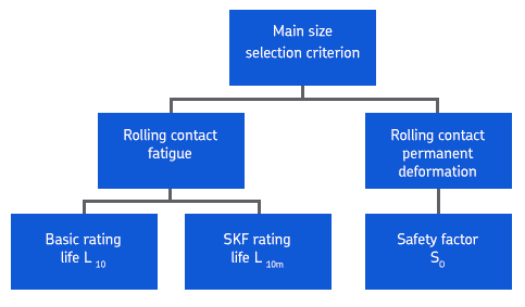
The above diagram shows these selection criteria and the related bearing ratings and static safety factor, which are described in detail in the relevant sub-sections. Which selection criteria you should use depends on the operating conditions of the bearing:
For applications where bearings are running in typical operating conditions – i.e. normal speeds, good lubrication conditions and not highly or peak loaded. – use Size selection based on rating life.
For applications where bearings are running under very low speeds or which are used under stationary conditions, very bad lubrication conditions or where occasional peak loads occur, use Size selection based on static load.
Note that there are applications where both selection criteria must be considered, for example where a duty cycle has occasional peak loads. Also, in applications where the bearing is lightly loaded, the minimum load requirement must also be considered.
After determining bearing size, and before going to the next step, check the items listed as below.
- grease life for capped bearings
- allowed axial/radial loads and Fa/Fr ratios
- minimum load
- adjusted reference speed and limiting speed
- misalignment
- stabilization class