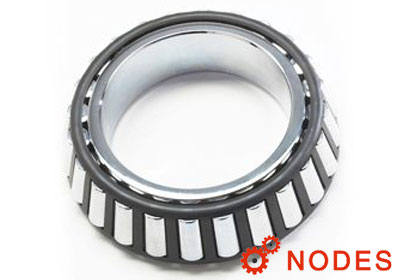
The original system developed by The Timken Company was based on a family of bearings designed around a common roller. Varying the number of rollers and the angle of the raceways allows different bearings to be designed for predominantly radial loads (shallow angle) or thrust loads (steep angle).
For example, all the TIMKEN tapered roller bearings in the 500 family use the same roller. However, the 595 Series has a steep angle and 24 rollers while the 525 Series has a shallow angle and 15 rollers.
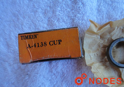
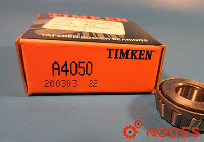
Individual part numbers are assigned to the inner and outer rings. Although there are exceptions, the general rule is that the outer ring has a part number that is lower than that of the inner ring.
ABMA inch PAR T-NUMBERING system
The current inch part-numbering system was developed by the American Bearing Manufacturers Association (ABMA) to address the expansion in the number of new applications and tapered roller-bearing designs. This part-numbering system has become the international standard for inch-sized bearings.
The ABMA part-numbering system has been applied only to new bearing series designed after its introduction. Other partnumbering systems also are in use including those based on the original numbering system and proprietary part numbers for special bearings.
For example:
HM 5 226 49 ---
- HM: series prefix
- 5: angularity
- 226: basic series indication
- 49: component designator
- ---: modification suffix
1, Series prefix
The series prefix consists of one or two letters that designate the duty class for which the bearing is designed.
| Prefix | Class Designation |
|---|---|
| EL | Extra Light |
| LL | Lighter than light |
| L | Light |
| LM | Light Medium |
| M | Medium |
| HM | Heavy Medium |
| H | Heavy |
| HH | Heavier than Heavy |
| EH | Extra Heavy |
| T | Thrust only |
2, Angularity designator
The first digit following the prefix represents the angle coding as determined by the included angle of the outer ring.
| Included Outer - Ring Angle | Code |
|---|---|
| 0° to 23° 59’ 59.99 in. | 1 |
| 24° to 25° 29’ 59.99 in. | 2 |
| 25° 30’ to 26° 59’ 59.99 in. | 3 |
| 27° to 28° 29’ 59.99 in. | 4 |
| 28° 30’ to 30° 29’ 59.99 in. | 5 |
| 30° 30’ to 32° 29’ 59.99 in. | 6 |
| 32° 30’ to 35° 59’ 59.99 in. | 7 |
| 36° to 44° 59’ 59.99 in. | 8 |
| 45° and over; excluding thrust | 9 |
3, Basic series indication
The two or three digits following the angularity designator are reserved for the basic series indication. Refer to ABMA standard 19.2 for more information.
Basic series is an indication of bore size, not the actual bore size. Large number = Larger bore.
4, Component designator
The last two numerical digits indicate the component number.
5, Modification suffix letters
The suffix may consist of one to three letters in pre-arranged combinations, indicating modifications in external form or internal arrangement.