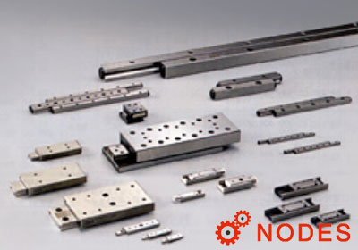
For selection of IKO crossed roller way guides CRW series specifications, stroke length and the number of cylindrical rollers, as well as accuracy, load rating and allowable load, must be determined.
Stroke length and the number of cylindrical rollers
Stroke length of the CRW series affects the way length and the number of cylindrical rollers.
Therefore, select specifications by following the procedure below taking into account the stroke length used and applied load.
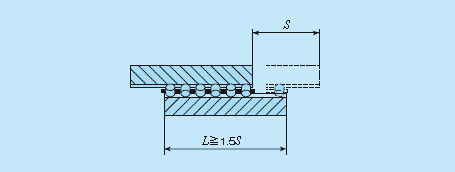
1, Calculation of way length
The way length, which should be 1.5 times longer than the stroke length used, is obtained from the equation below.
L ≧ 1.5S
- L: Way length mm
- S: Stroke length used mm
2, Calculation of maximum stroke length
Ideally the stroke length used should be less than 80% of the maximum stroke length, which is obtained from the equation below.
S1 ≧ 1/0.8S
- S1: Maximum stroke length mm
- S: Stroke length used mm
3, Calculation of cage length and the number of rollers
With the way length and maximum stroke length determined, the allowable length for cage can be calculated. Calculation method of the cage length varies depending on specifications of end screws and end stopper fitted to the way end.
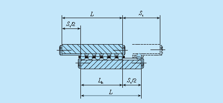
(1) With standard end screws and end stopper SA (excluding Size 1 series) The dimensions between rollers at both ends is obtained from the following equation by using a value obtained by subtracting a half of the maximum stroke length from the way length.
LR = L - S1/2
- LR: Allowable dimensions between rollers at both ends mm
- L: Way length mm
- S1: Maximum stroke length mm
The number of rollers to be incorporated in a roller cage is obtained by the following equation.
Z = (LR - DW)/P + 1
- Z: Number of cylindrical rollers (figures after the decimal fractions are omitted)
- LR: Allowed dimensions between rollers at both ends mm
- DW: Diameter of cylindrical rollers (refer to the dimension table) mm
- P: Inter-pitch dimensions of cylindrical rollers (refer to the dimension table) mm
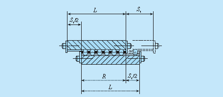
(2) For Size 1 series
The stroke length is regulated by cage and end stopper and the cage length is obtained by the following equation.
R = L - S1/2
- R: allowable cage length mm
- L: Way length mm
- S1: Maximum stroke length mm
The number of rollers to be incorporated in a roller cage is obtained by the following equation.
Z = (R - 2e) / P + 1
- Z: Number of cylindrical rollers (figures after the decimal fractions are omitted)
- R: Allowable cage length mm
- e: End dimension of cage (refer to the IKO crossed roller ways dimension table) mm
- P: Inter-pitch dimensions of cylindrical rollers (refer to the dimension table) mm
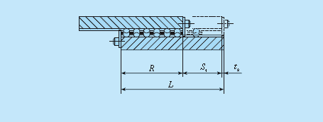
(3) For end stopper SB and wiper seal
The stroke length is regulated by cage and end stopper or wiper seal and the cage length is obtained by the following equation.
R = L - t2 - S1
- R: Allowable cage length mm
- L: Way length mm
- S1: Maximum stroke length mm
- t2: Thickness of end stopper SB or wiper seal mm
The number of rollers to be incorporated in a roller cage is obtained by the equation (18) as with the Size 1 series.