
Mounting surface, reference mounting surface and general mounting structure
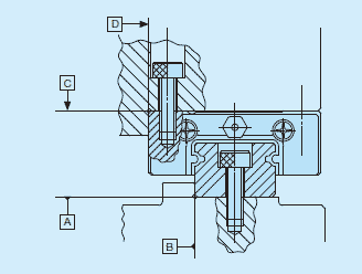
When mounting IKO ML(F) series and LWL(F) series, properly align the reference mounting surfaces B and D (D1 or D2)of the track rail and slide unit with the reference mounting surface of the table and bed and fix them.
Reference mounting surfaces B and D (D1 or D2) and mounting surfaces A and C are precisely ground. By machining the mounting surface of the mating member, such as machine or device, to high accuracy and mounting them properly, stable linear motion with high accuracy is obtained.
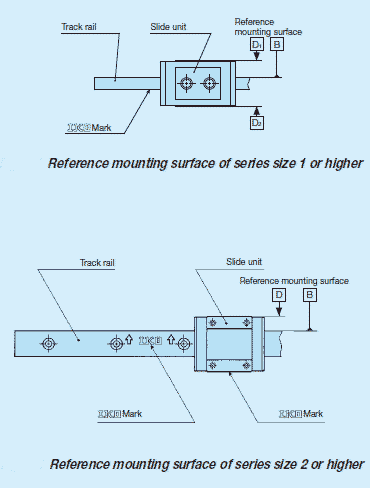
Reference mounting surface of IKO slide unit of size 2 or higher is the opposite side of the IKO mark. The track rail reference mounting surface is identified by locating the mark on the top surface of the track rail. It is the side surface above the mark (in the direction of the arrow).
Reference mounting surface of the slide unit of size 1 is located at both right and left sides (D1 and D2).
The track rail of LWL1…Y has the mounting structure of lateral direction.
Mounting screws for slide unit
To mount a slide unit, tightly fasten the bolt against female thread of slide unit.
The female thread is created through holes of the slide unit for size 1 series, and also through holes for the slide unit and track rail for size 2, 3, 4 and 6 series. When the fixing thread depth of the mounting screw goes too deep, it can interfere with the track rail and impact the running accuracy or product life so that the fixing thread depth should be within the screwing depth specified in the dimension table. Also prepare the small screws dedicated to precision devices (head diameter 1.8 mm or smaller) for the mounting bolt of slide unit of size 1.
Mounting screws for track rail
In the size 2 and 3 series and tapped rail specifications, track rail mounting bolts are not appended. Prepare mounting bolts whose fixing thread depth is less than H4
Shoulder height and corner radius of the reference mounting surface
For the opposite corner of the mating reference mounting, it is recommended to have relieved fillet as indicated.
Tightening torque for fixing screw
Typical tightening torque for mounting ML(F) series and LWL(F) series to the steel mating member material is indicated in Table below. When vibration and shock of the machine or device are large, fluctuating load is large, or moment load is applied, fix it by using the torque 1.2 to 1.5 times larger than the value indicated in the table as necessary. If the mating member material is cast iron or aluminum alloy, reduce the tightening torque depending on the strength characteristics of the mating member material.
| Bolt size | Tightening torque N・m | |
|---|---|---|
| Stainless steelmade screw | High carbon steelmade screw | |
| M1 ×0.25 | 0.04 | - |
| M1.4×0.3 | 0.10 | - |
| M1.6×0.35 | 0.15 | - |
| M2 ×0.4 | 0.31 | - |
| M2.5×0.45 | 0.62 | - |
| M3 ×0.5 | 1.1 | 1.3 |
| M4 ×0.7 | 2.5 | 2.9 |
| M5 ×0.8 | 5.0 | 5.7 |
| M6 ×1 | 8.5 | - |