1, Handling
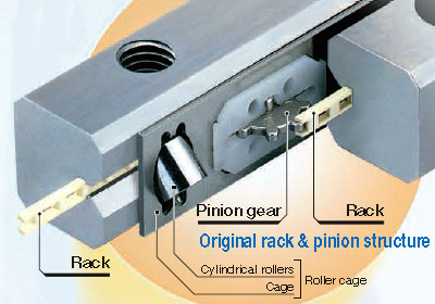
As the IKO CRWG series, CRWG...H series and CRW series are designed highly precisely, take extra care for handling. A pinion gear and cylindrical roller are incorporated with the cage for the CRWG series and CRWG...H series. When the cage is dropped or handled roughly, the pinion gear and cylindrical roller may come off. Especially for CRWG...H, grabbing the cylindrical roller may take it off, so be sure to hold the cage body for handling. In addition, do not cut off the cage as doing so may cause pinion gear coming off and breakage of gear joint section.
A rack is incorporated with the way for the CRWG series and CRWG...H series. In operation, take note that the rack may come off when the end screw is removed. Though the cage for the CRW series may cut off to necessary length, handle it with care not to deform it when cutting.
2, Accuracy of mounting part
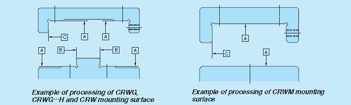
Examples of typical mounting surface processing
General processing accuracy of mounting surface is according to table as follows. However, care should be exercised as mounting surface accuracy directly affects running accuracy. Especially when high running accuracy is required, the processing accuracy higher than that indicated in table as follows is required.
| Accuracy of A surface | Directly affects running accuracy. For the flatness of two mounting surfaces on table and bed sides, allowable value approximate to the parallelism |
| Accuracy of B and C surfaces |
Flatness Affects preload Squareness Affects rigidity in preload direction of the mounting part of the CRWG series, CRWG...H series and CRW series. Process to sufficiently high accuracy. |
3, Shape of mounting part
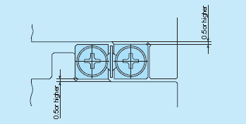
For the opposite corner of the mating reference mounting, it is recommended to have relieved fillet as indicated in drawing above. In addition, a clearance of 0.5 mm or higher should be made between the way and the mating member material.
4, Preload adjustment mechanism
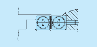
For use with preload, use the preload adjusting screw as indicated in drawing above as a general way. Preload adjusting screw nominal dimensions and mounting position should be in accordance with the way fixing bolt dimensions and position. Press the center of the way H dimensions.
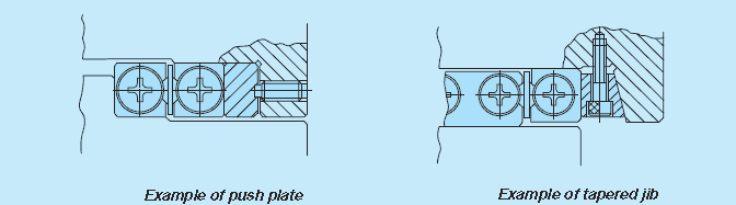
Preload amount varies depending on operational conditions of your machine and device. However, as excessive preload may lead to short life and damage on the raceway, it is typically ideal to adjust to zero clearance or slight preload state. When accuracy and rigidity are required, use a push plate or tapered jib as indicated in drawing above, respectively.
5, Operating temperature
As synthetic resin components are used for the CRWG series and CRWG...H series, the maximum operating temperature is 120°C, while it should be lower than 100°C for continuous use. As synthetic resin components are not used for the CRW series, it may be used at high temperature. However, when it exceeds 100°C, contact IKO
6, Maximum velocity
Operating velocity should be lower than 50 m/min for the CRWG series and CRWG...H series, and lower than 30 m/ min for the CRW series.
7, Tightening torque for fixing screw
Typical tightening torque for mounting of the CRWG series, CRWG...H series and CRW series is indicated in Table as below. When vibration and shock are large or moment load is applied, it is recommended to fix by using the torque 1.3 times larger than that indicated in the table. In addition, when high running accuracy is required with no vibration and shock, it may be fixed by using torque smaller than that indicated in the table, however, it is recommended to use adhesive agent to fasten the screw, or to use stop bolts.
| Bolt size |
Tightening torque N.m |
|---|---|
| M 2 x 0.4 | 0.4 |
| M3 X 0.5 | 1.4 |
| M4 X 0.7 | 3.2 |
| M5 X 0.8 | 6.4 |
| M6 X 1 | 10.9 |
| M8 X 1.25 | 26.1 |
| M10 X 1.5 | 51.1 |
| M12 X 1.75 | 88.2 |
| M14 X 2 | 140 |
| M16 X 2 | 215 |