1, Lubrication
Grease is not pre-packed in the IKO CRWUG series and CRWU series crossed roller way units, so please perform adequate lubrication as needed. Both of oil lubrication and grease lubrication are available in the CRWUG series and CRWU series. Generally, oil lubrication should be selected for high speed or low frictional resistance, and grease lubrication for low speed. For grease lubrication, use of high-quality lithium-soap base grease is recommended.
2, Dust Protection
Since the IKO CRWUG series and CRWU series are finished with high accuracy, harmful foreign substances such as dust and particles entering into the bearing will cause low life or impaired accuracy. For applications in other than clean environment, cover the entire unit with a protective case, etc. to prevent harmful foreign substances such as dust, particles and water from outside from entering.
3, Handing
As the CRWUG series and CRWU series are designed highly precisely, take extra care for handling.
Cage of the IKO CRWUG series has a pinion gear incorporated. When the cage is dropped or handled roughly, the pinion gear may come off. In addition, do not cut off the cage as doing so may cause pinion gear coming off and breakage of gear joint section.
Way of the CRWUG series has a rack incorporated. In operation, take note that the rack may come off when the end screw is removed.
For the CRWU series, the cage may be deviated from the right position due to offset load or irregular and high-velocity motion, etc. Fully stroke it once in certain operating time or certain number of reciprocating motion to correct the cage position.
4, Preload re-adjustment
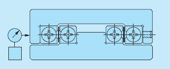
Example of preload adjustment method
Preload amount of the CRWUG series and CRWU series is adjusted to zero or slight preload state, so they may be used as they are.
Preload amount of the CRWUG series, CRWU, and CRWU… R may be re-adjusted by following the procedure below. Preload adjustment is started from the preload adjusting screw at the center of way length and then both ends in turn, with fixing screws of the preload adjusting side way temporarily fixed.
While measuring the clearance on the table sides, tighten the preload adjusting screws subsequently until deflection of the dial gauge stops. Measure the tightening torque for preload adjusting screws at this point.
When adjusting preload adjusting screw near either end, stroke the table softly and check that the cylindrical roller is on the preload adjusting screw section.
After the above procedure, the clearance becomes zero or in slight preload state, but preload is still not adjusted evenly. With the same procedure again, re-adjust all the preload adjusting screws evenly to the torque previously measured.
5, Operating temperature
As synthetic resin components are used for the CRWUG series, the maximum operating temperature is 120°C, while it should be lower than 100°C for continuous use. As synthetic resin components are not used for the CRWU series, it may be used at high temperature.
6, Maximum velocity
Operating velocity should not exceed 30 m/min during operation.
7, Tightening torque for fixing screw
The table below shows typical tightening torque for mounting CRWUG Series and CRWU Series. When vibration and shock are large or moment load is appl ied, it is recommended to fix by using the torque 1.3 times larger than that indicated in the table. In addition, when high running accuracy is required with no vibration and shock, it may be fixed by using torque smaller than that indicated in the table, however, it is recommended to use adhesive agent to fasten the screw, or to use stop bolts.
| Bolt size |
Tightening torque N・m |
|---|---|
| M 2 X0.4 | 0.4 |
| M 2.5 X0.5 | 0.8 |
| M3 X0.5 | 1.4 |
| M4 X0.7 | 3.2 |
| M5 X0.8 | 6.4 |
| M6 X1 | 10.9 |
| M8 X1.25 | 26.1 |
8, Dowel pin hole of CRWU...R
dowel pin hole is machined on the center way of the CRWU…R. When a dowel pin is used, machine a hole on the mounting surface of the machine after mounting of the center way.
Refer to the dimension table for diameter and its tolerances of dowel pin hole of the center way.
9, Mounting part dimensions of CRWU...R
Not to allow the table to interfere with the mounting surface, it is necessary to set mounting surface height referring to the dimensions H1 and H in the dimension table. Example bed mounting dimensions are indicated in Table below.
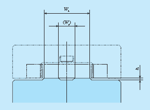
| Identification number | h( minimum) | W3 | W4 |
|---|---|---|---|
| CRWU 30 ...R | 0.5 | 13 | - |
| CRWU 40 ...35R | 0.5 | 18 | - |
| CRWU 40 ...R | 13 | - | |
| CRWU 60 ...R | 0.5 | 26.5 | - |
| CRWU 80 ...R | 0.5 | 38 | 16 |
| CRWU100 ...R | 0.5 | 42 | 14 |
| CRWU145 ...R | 1.0 | 68.5 | 28.5 |