Previous versions of Kaydon catalog have discussed applying the loads from a free body diagram to a Kaydon thin section ball bearing system and solving for each of four reactions. As there are generally three equations (one for radial, one for axial, one for moment loads) and four unknowns, one of the reactions has been assumed to be zero. Once the remaining reactions are resolved, the life of the bearing can be determined.
This method had several drawbacks, including:
- It suggested very low bearing life for systems with predominantly axial loads.
- Internal bearing fitup could not be included in the life calculation.
- All loading was assumed to be distributed around the bearing as though it were a pure radial load… regardless of its origin.
Modern computers and software allow for a more complicated and accurate method of determining life. Illustrated here are the results of this process. The actual loads are applied to the Kaydon bearing and the resultant load on each and every ball in that bearing is determined. From this data, the static safety factor and dynamic L10 life can be determined.
To better understand this, the following should be considered:
Primary radial loading
- Larger clearances will have fewer balls carrying the loads, resulting in lower dynamic lives.
- Larger preloads may overload the Kaydon bearing before the loads are applied.
Primary axial and moment loading
- Larger clearances will permit a higher contact angle than the ball has with the raceway, and thus better support the applied loading.
- However, the ball-to-raceway contact area may spill over the edge of the race, causing other problems.
- Larger preloads may again overload the bearing before the loads are applied.
The method for calculating either a static safety factor or dynamic life requires a computer to determine the individual ball loads throughout the bearing. When these have been calculated, the maximum loaded ball is used to determine a maximum stress level and thus a static safety factor. All of the ball loads are used in a weighted analysis to determine the dynamic L10 life.
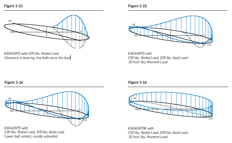
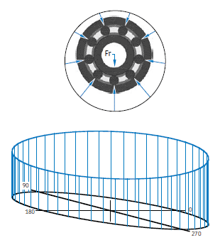
To better understand these principles, graphical representations of ball distribution around each of three common bearing types are shown in Figures below. Here the ball load distribution and magnitude can be visualized. The higher the peak, the higher the loads.
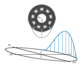
KA040CP0 with 100 lbs. radial load Clearance in the bearing; few balls carry the load.
This Kaydon radial bearing contains clearance. There are only three balls supporting this load, with a very high maximum value for the bottom ball.
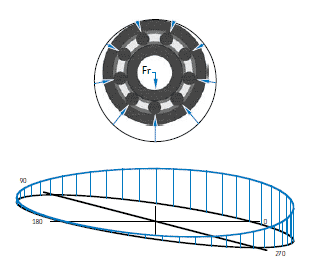
KA040CP0K with 100 lbs. radial load Light preload in the bearing; all balls carry the load.
This Kaydon radial bearing contains a light preload. All the balls have some load on them and, as can be seen, the bottom middle ball has far less load than the example above.
KA040CP0P with 100 lbs. radial load. Heavy preload.
This radial contact bearing contains a very heavy preload. All the balls have load on them, and the load on the bottom ball is just as high as the bearing with clearance in the first example.
More diagrams are shown below for other instances