Operating clearance of INA spherical plain bearings
The operating clearance or preload is determined on a fitted bearing still warm from operation.
It is derived from the radial internal clearance and the change in the radial internal clearance as a result of interference fit and thermal influences in the fitted condition.
Internal clearance of INA radial spherical plain bearings
The radial and axial internal clearance is determined on the dismounted bearing.
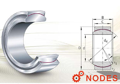
The radial internal clearance of radial spherical plain bearings is defined as the distance by which the inner ring can be moved in a radial direction relative to the outer ring from one extreme position to the precisely opposite extreme position.
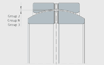
Radial internal clearance of INA spherical plain bearings
INA maintenance-free spherical plain bearings
Maintenance-free spherical plain bearings have a very small internal clearance, see dimension tables. As a result, preloads may be present once the bearing is fitted.
INA spherical plain bearings requiring maintenance
The radial internal clearance is subdivided into three groups in accordance with DIN ISO 12240-1, see table. The precondition is a housing bore that causes no dimensional changes in the INA bearing with the exception of geometrical inaccuracies.
INA radial internal clearance
INA radial internal clearance groups
| Internal clearance group in accordance with ISO 12240-1 | Description | Application range |
|---|---|---|
|
Group N (CN) |
Normal internal clearance; CN is not included in bearing designations | Under normal operating conditions and with the recommended fits, this gives optimum operating clearance |
|
Group 2 (C2) |
Internal clearance < CN (suffix C2) | For bearing arrangements with very small clearance |
|
Group 3 (C3) |
Internal clearance > CN (suffix C3) | For bearing rings with press fits or a large temperature differential between the inner and outer ring |
INA radial internal clearance
| Series |
Radial internal clearance um |
||||||
|---|---|---|---|---|---|---|---|
|
GE..-DO GE..-DO-2RS(-2TS) GE..-HO-2RS GE..-LO |
GE..-FO GE..-FO-2RS(-2TS) |
Group 2 (C2) |
Group N (CN) |
Group 3 (C3) |
|||
|
Bore d mm |
min. | max. | min. | max. | min. | max. | |
| 6 | 6 | 8 | 32 | 32 | 68 | 68 | 104 |
| 8 | 8 | 8 | 32 | 32 | 68 | 68 | 104 |
| 10 | 10 | 8 | 32 | 32 | 68 | 68 | 104 |
| 12 | - | 8 | 32 | 32 | 68 | 68 | 104 |
| - | 12 | 10 | 40 | 40 | 82 | 82 | 124 |
| 15 | 15 | 10 | 40 | 40 | 82 | 82 | 124 |
| 16 | - | 10 | 40 | 40 | 82 | 82 | 124 |
| 17 | 17 | 10 | 40 | 40 | 82 | 82 | 124 |
| 20 | - | 10 | 40 | 40 | 82 | 82 | 124 |
| - | 20 | 12 | 50 | 50 | 100 | 100 | 150 |
| 25 | 25 | 12 | 50 | 50 | 100 | 100 | 150 |
| 30 | 30 | 12 | 50 | 50 | 100 | 100 | 150 |
| 32 | - | 12 | 50 | 50 | 100 | 100 | 150 |
| 35 | - | 12 | 50 | 50 | 100 | 100 | 150 |
| - | 35 | 15 | 60 | 60 | 120 | 120 | 150 |
| 40 | 40 | 15 | 60 | 60 | 120 | 120 | 180 |
| 45 | 45 | 15 | 60 | 60 | 120 | 120 | 180 |
| 50 | 50 | 15 | 60 | 60 | 120 | 120 | 180 |
| 60 | - | 15 | 60 | 60 | 120 | 120 | 180 |
| - | 60 | 18 | 72 | 72 | 142 | 142 | 212 |
| 63 | - | 18 | 72 | 72 | 142 | 142 | 212 |
| 70 | 70 | 18 | 72 | 72 | 142 | 142 | 212 |
| 80 | 80 | 18 | 72 | 72 | 142 | 142 | 212 |
| 90 | - | 18 | 72 | 72 | 142 | 142 | 212 |
| - | 90 | 18 | 85 | 85 | 165 | 165 | 245 |
| 100 | 100 | 18 | 85 | 85 | 165 | 165 | 245 |
| 110 | 110 | 18 | 85 | 85 | 165 | 165 | 245 |
| 120 | 120 | 18 | 85 | 85 | 165 | 165 | 245 |
| 140 | - | 18 | 85 | 85 | 165 | 165 | 245 |
| 160 | 140 | 18 | 100 | 100 | 192 | 192 | 284 |
| 180 | 160 | 18 | 100 | 100 | 192 | 192 | 284 |
| 200 | 180 | 18 | 100 | 100 | 192 | 192 | 284 |
| - | 200 | 18 | 110 | 110 | 214 | 214 | 318 |
| 220 | 220 | 18 | 110 | 110 | 214 | 214 | 318 |
| 240 | - | 18 | 110 | 110 | 214 | 214 | 318 |
| 250 | 240 | 18 | 125 | 125 | 239 | 239 | 353 |
| 260 | 260 | 18 | 125 | 125 | 239 | 239 | 353 |
| 280 | 280 | 18 | 125 | 125 | 239 | 239 | 353 |
| 300 | - | 18 | 125 | 125 | 239 | 239 | 353 |
Axial internal clearance
The axial internal clearance is defined as the distance by which the inner ring can be moved in an axial direction relative to the outer ring from one extreme position to the precisely opposite extreme position.
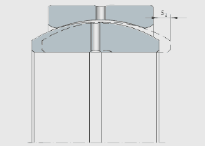
Axial internal clearance
It is dependent on the bearing geometry and is in a direct relationship with the radial internal clearance. Depending on the bearing type, it may be several times greater than the radial internal clearance.
Fit conditions for INA spherical plain bearings
The interference fits and clearance fits for practical use are determined from the corresponding ISO fit in conjunction with the normal bearing tolerances in accordance with DIN ISO 12240-1 to DIN ISO 12240-3, see tables. The actual dimensions must correspond to the centre tolerance.
Definitions:
– indicates an interference fit
+ indicates a clearance fit.
Shaft fits
For example: A shaft of diameter 50 m6 has a probable interference fit of 0,023 mm.
Interference fit ÜI or clearance fit
Nominal shaft diameter in mm
| over | 3 | 6 | 10 | 18 | 30 | 50 | 80 | 120 | 180 | 250 | 315 | 400 |
| incl. | 6 | 10 | 18 | 30 | 50 | 80 | 120 | 180 | 250 | 315 | 400 | 500 |
| Normal tolerance, interference fit or clearance fit in um(1 | ||||||||||||
| h6 | 0 | 0 | +1 | +1 | +2 | +2 | +1 | 0 | 0 | -2 | -2 | -2 |
| j6 | -6 | -7 | -7 | -8 | -9 | -10 | -13 | -14 | -17 | -17 | -20 | -22 |
| k6 | -9 | -9 | -9 | -14 | -16 | -20 | -24 | -28 | -30 | -33 | -38 | -42 |
| m6 | -12 | -15 | -17 | -20 | -23 | -28 | -34 | -40 | -47 | -53 | -59 | -65 |
| n6 | -16 | -19 | -22 | -27 | -31 | -37 | -44 | -52 | -61 | -67 | -75 | -82 |
1) Not applicable to series GE..-LO, GE..-PB, GE..-SX, GE..-PW and GE..-SW.
Housing fits
For example: A housing bore of diameter 75 M7 has a probable interference fit of 0,009 mm.
Interference fit ÜA or clearance fit
Nominal housing bore diameter in mm
| over | 6 | 10 | 18 | 30 | 50 | 80 | 120 | 150 | 180 | 250 | 315 | 400 |
| incl. | 10 | 18 | 30 | 50 | 80 | 120 | 150 | 180 | 250 | 315 | 400 | 500 |
| Normal tolerance, interference fit or clearance fit in um1) | ||||||||||||
| J7 | +4 | +5 | +6 | +7 | +10 | +12 | +15 | +18 | +22 | +27 | +31 | +34 |
| K7 | +1 | +1 | -1 | 0 | 0 | -1 | +1 | +4 | +5 | +7 | +8 | +8 |
| M7 | -4 | -5 | -7 | -8 | -9 | -11 | -11 | -8 | -8 | -9 | -9 | -10 |
| N7 | -8 | -10 | -14 | -16 | -18 | -21 | -23 | -20 | -22 | -23 | -25 | -27 |
1) Not applicable to series GE..-SX and GE..-SW.