Uniform support of the bearing rings by the adjacent construction
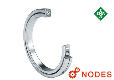
INA crossed roller bearings SX can support high loads. Due to the X arrangement of the cylindrical rollers, these bearings can support axial forces in both directions, radial loads, tiltingmoment loads and any combinations of loads. In order that these advantages can be utilised comprehensively, the adjacent construction must be designed so that it is appropriately rigid. The bearing rings must always be rigidly and uniformly supported over the circumference and width of the rings.
The adjacent construction must be designed only in accordance with the information in this section. Any deviations from the specifications, material strength and adjacent components will considerably reduce the load carrying capacity and operating lifeof the bearings.
Shart and housing tolerances for INA crossed roller bearing
For normal applications, the tolerance class K7 for the housing and h7 for the shaft are sufficient, please see the table below.
In precision applications, the bearing seat in the housing should be designed to tolerance class K6 and on the shaft to h6.
Mounting tolerances for the shaft
|
Nominal dimension di |
Tolerance classes | ||||
|---|---|---|---|---|---|
| mm | |||||
| > | ≦ | h6 | h7 | ||
| Upper deviation | Lower deviation | Upper deviation | Lower deviation | ||
| μm | μm | μm | μm | ||
| 65 | 80 | 0 | –19 | 0 | –30 |
| 80 | 100 | 0 | –22 | 0 | –35 |
| 100 | 120 | 0 | –22 | 0 | –35 |
| 120 | 140 | 0 | –25 | 0 | –40 |
| 140 | 160 | 0 | –25 | 0 | –40 |
| 160 | 180 | 0 | –25 | 0 | –40 |
| continued | |||||
|
Nominal dimension di |
Tolerance classes | ||||
|---|---|---|---|---|---|
| mm | |||||
| > | ≦ | h6 | h7 | ||
| Upper deviation | Lower deviation | Upper deviation | Lower deviation | ||
| μm | μm | μm | μm | ||
| 180 | 200 | 0 | –29 | 0 | –46 |
| 200 | 225 | 0 | –29 | 0 | –46 |
| 225 | 250 | 0 | –29 | 0 | –46 |
| 250 | 280 | 0 | –32 | 0 | –52 |
| 280 | 315 | 0 | –32 | 0 | –52 |
| 315 | 355 | 0 | –36 | 0 | –57 |
| 355 | 400 | 0 | –36 | 0 | –57 |
| 400 | 450 | 0 | –40 | 0 | –63 |
| 450 | 500 | 0 | –40 | 0 | –63 |
Mounting tolerances for the housing bore
|
Nominal dimension Da |
Tolerance classes | ||||
|---|---|---|---|---|---|
| mm | |||||
| > | ≦ | K6 | K7 | ||
| Upper deviation | Lower deviation | Upper deviation | Lower deviation | ||
| μm | μm | μm | μm | ||
| 80 | 100 | +4 | –18 | +10 | –25 |
| 100 | 120 | +4 | –18 | +10 | –25 |
| 120 | 140 | +4 | –21 | +12 | –28 |
| 140 | 160 | +4 | –21 | +12 | –28 |
| 160 | 180 | +4 | –21 | +12 | –28 |
| 180 | 200 | +5 | –24 | +13 | –33 |
| 200 | 225 | +5 | –24 | +13 | –33 |
| 225 | 250 | +5 | –24 | +13 | –33 |
| 250 | 280 | +5 | –27 | +16 | –36 |
| 280 | 315 | +5 | –27 | +16 | –36 |
| 315 | 355 | +7 | –29 | +17 | –40 |
| 355 | 400 | +7 | –29 | +17 | –40 |
| 400 | 450 | +8 | –32 | +18 | –45 |
| 450 | 500 | +8 | –32 | +18 | –45 |
| 500 | 560 | 0 | –44 | 0 | –70 |
| 560 | 630 | 0 | –44 | 0 | –70 |
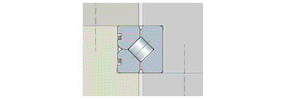
Location using clamping rings
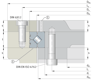
Clamping rings, bearing seat depth, mounting dimensions
1) Slots, threaded extraction hole or similar for dismounting purposes
For the location of crossed roller bearings SX, clamping rings have proved effective. The bearing rings must always be rigidly and uniformly supported over the circumference and width of the rings. The thickness of the clamping rings and mounting flanges must not be less than the minimum thickness s. Counterbores to DIN 74, type J, for screws to DIN 6912 are permissible. For deeper counterbores, the thickness of the clamping ring s must be increased by the additional counterbore depth.
INA crossed roller bearing seat depth
In order that the clamping rings retain the bearing securely, the bearing seat depth t must be in accordance with the specification, please see the table below.
The depth of the bearing seat influences the bearing clearanceand the rotational resistance. Bearings with preload (suffix VSP) have a considerably higher rotational resistance.
If particular requirements for rotational resistance apply, the depth t must be produced to match the relevant height of the bearing ring. It has proved effective to tolerance the depth t to deviations that are the same as or further restricted compared to the dimension h in the product tables. For safety, internal tests should in any case be carried out.
Minimum strength of clamping rings
For screws of grade 10.9, the minimum strength under the screw heads or nuts must be 500 N/mm2. Seating washers are not necessary for these screws.
For fixing screws of grade 12.9, the minimum strength must not be less than 850 N/mm2, otherwise quenched and tempered seating washers under the screw heads or quenched and tempered nuts must be used.
| Designation | Mounting dimensions in mm | ||||||||||
|---|---|---|---|---|---|---|---|---|---|---|---|
| di | Da | t | s | dRa | dRi | DRi | DRa | Li | La | ||
|
h7 (h6) |
K7 (K6) |
min. |
max. |
min. |
|||||||
| SX011814 | 70 | 90 | 10 | –0,005–0,015 | 8 | 78 | 42 | 82 | 118 | 60 | 100 |
| SX011818 | 90 | 115 | 13 | –0,005–0,020 | 10 | 100 | 61 | 104 | 144 | 80 | 125 |
| SX011820 | 100 | 125 | 13 | –0,005–0,020 | 10 | 110 | 71 | 114 | 154 | 90 | 135 |
| SX011824 | 120 | 150 | 16 | –0,005–0,025 | 12 | 132 | 84 | 138 | 186 | 108 | 162 |
| SX011828 | 140 | 175 | 18 | –0,005–0,030 | 14 | 154 | 94 | 160 | 221 | 124 | 191 |
| SX011832 | 160 | 200 | 20 | –0,02–0,05 | 15 | 177 | 111 | 183 | 249 | 144 | 216 |
| SX011836 | 180 | 225 | 22 | –0,02–0,05 | 17 | 199 | 121 | 205 | 284 | 160 | 245 |
| SX011840 | 200 | 250 | 24 | –0,02–0,06 | 18 | 221 | 139 | 229 | 311 | 180 | 270 |
| SX011848 | 240 | 300 | 28 | –0,02–0,06 | 21 | 269 | 166 | 274 | 374 | 216 | 324 |
| SX011860 | 300 | 380 | 38 | –0,04–0,10 | 29 | 335 | 201 | 345 | 479 | 268 | 412 |
| SX011868 | 340 | 420 | 38 | –0,04–0,10 | 29 | 375 | 241 | 385 | 519 | 308 | 452 |
| SX011880 | 400 | 500 | 46 | –0,04–0,10 | 35 | 445 | 275 | 455 | 625 | 360 | 540 |
| SX0118/500 | 500 | 620 | 56 | –0,04–0,10 | 42 | 554 | 350 | 566 | 700 | 452 | 668 |
Fixing screws
For the location of the bearing rings or clamping rings, screws of grade 10.9 are suitable, please see the table below.
Fixing screws
| Crossed roller bearings |
Fixing screws Grade 10.9 |
Tightening torque | |
|---|---|---|---|
| Dimension | Quantity |
MA Nm |
|
| SX011814 | M5 | 18 | 7 |
| SX011818 | M5 | 24 | 7 |
| SX011820 | M5 | 24 | 7 |
| SX011824 | M6 | 24 | 11,7 |
| SX011828 | M8 | 24 | 27,8 |
| SX011832 | M8 | 24 | 27,8 |
| SX011836 | M10 | 24 | 55,6 |
| SX011840 | M10 | 24 | 55,6 |
| SX011848 | M12 | 24 | 98,4 |
| SX011860 | M16 | 24 | 247 |
| SX011868 | M16 | 24 | 247 |
| SX011880 | M20 | 24 | 481 |
| SX0118/500 | M24 | 24 | 831 |